Friday, September 18, 2015

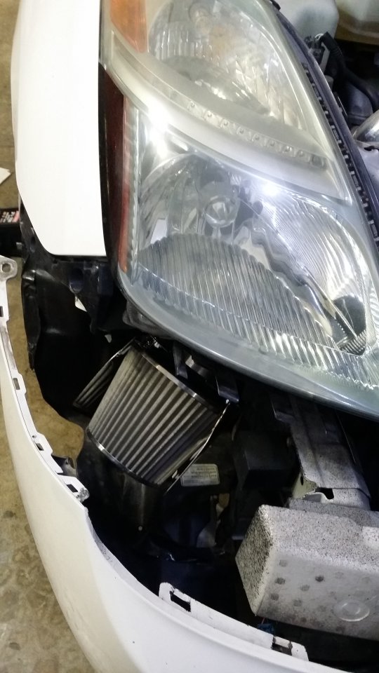
Sezy Cold Air Intake

Sezy Cold Air Intake


Was able to snag an extra air box from this Prius at a junk yard.


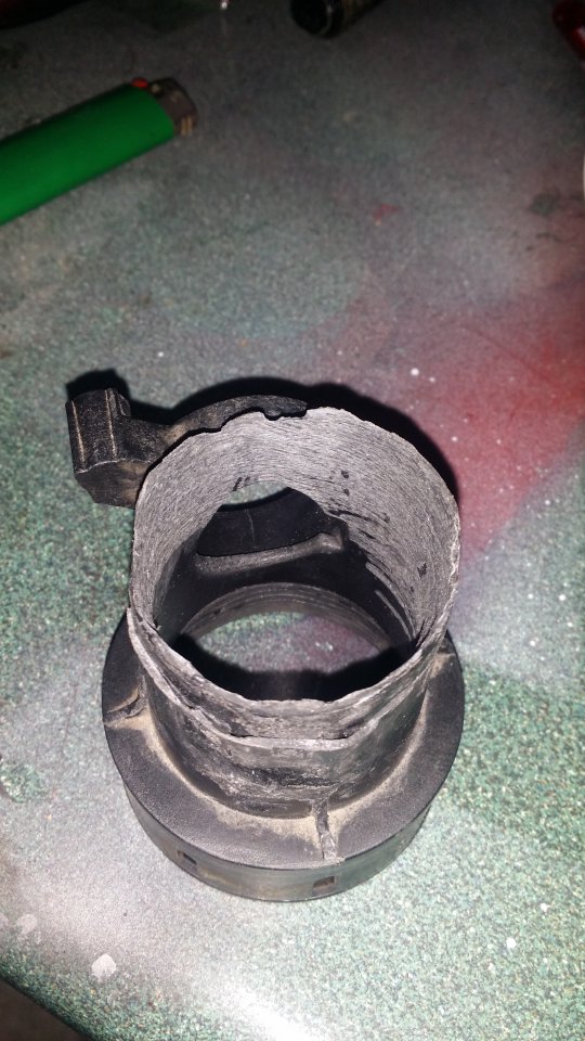
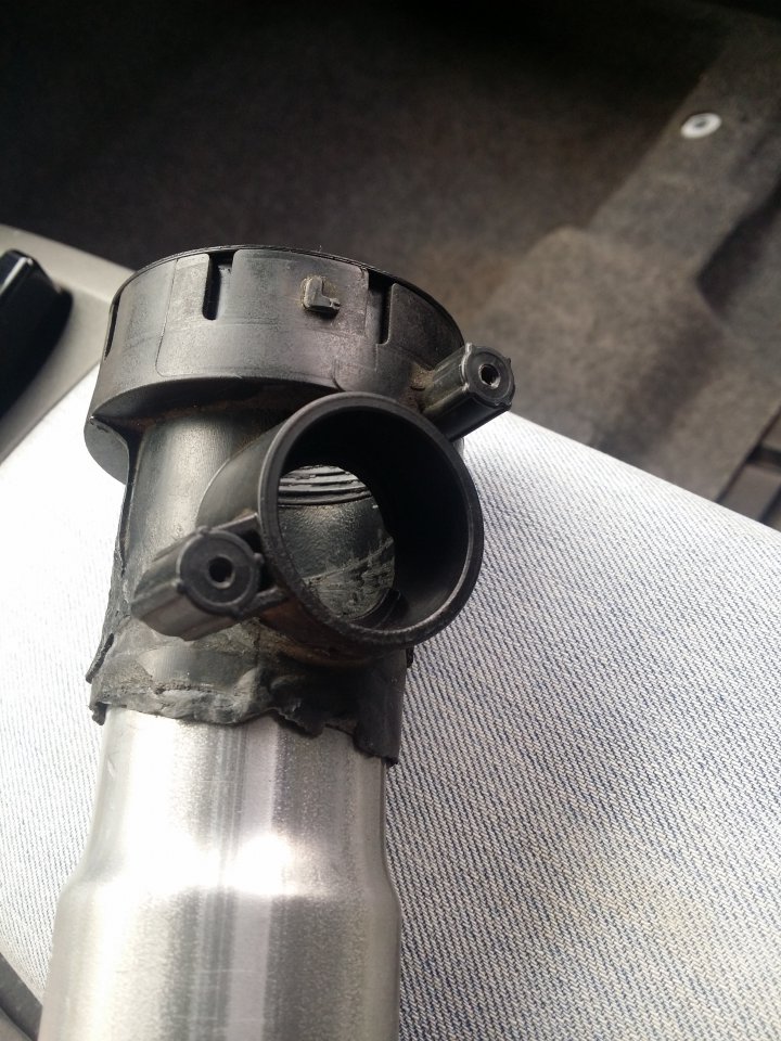
First make large cuts to remove the MAF housing and the extra tube that connects to the OEM air hose. The MAF is oddly shaped and would not allow for anything else to clamp onto it. The air intake side part will be used to fix this issue.


I took a torch the the ends of the MAF and extra part then with a flat head screw driver started molding/pulling the melted plastic. Make sure there are no air holes or leaks. I would heat it ,mold a little then cool it off in water until I got the desired result. Used a dremel inside after wards to smooth out the inside and grinded the outside to get any plastic clumps off.


Some of the parts I ordered. Only thing missing is a small cone air filer.


 First parts to arrive. 2" to 2.25" elbow fits fine.

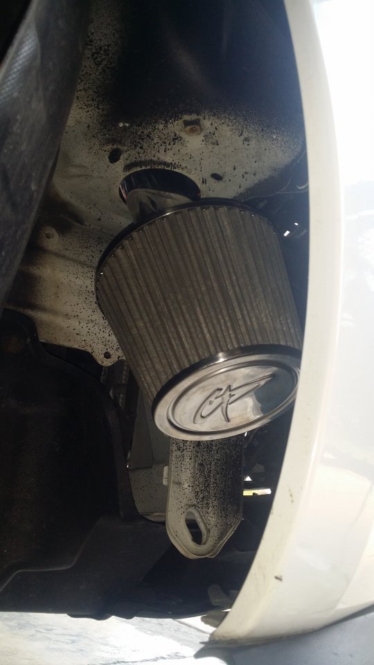
Filter came in next. Had to remove the hood insulator for this to fit. Waiting on the tubing to come in. Sounds meaner already.


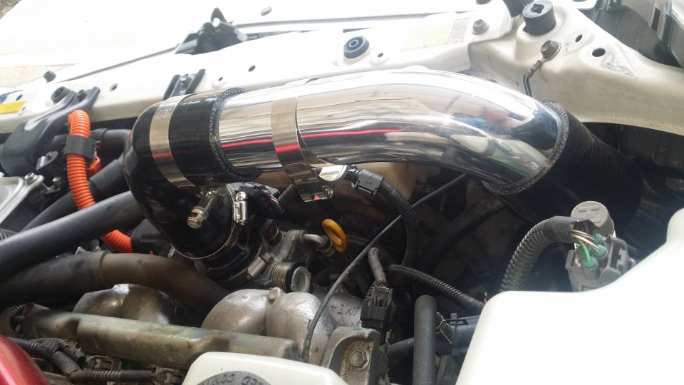
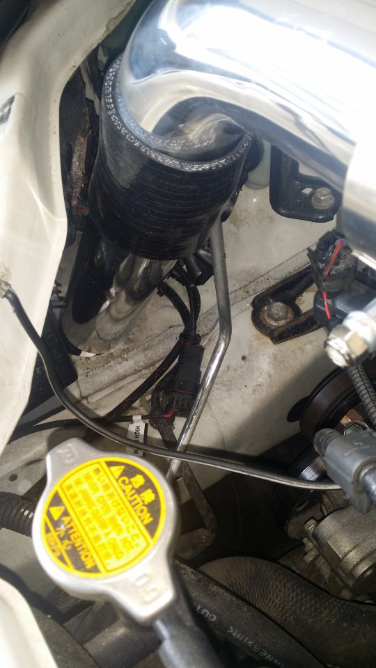
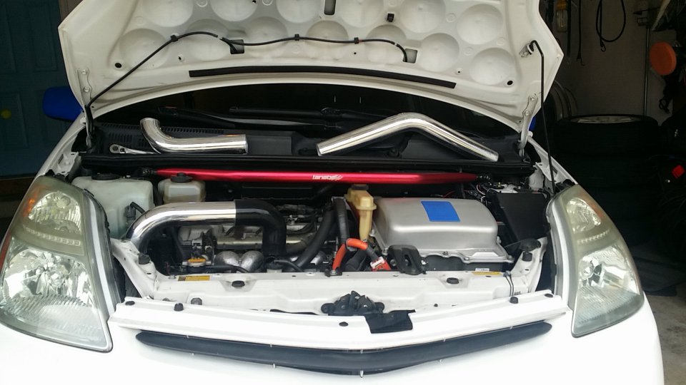
Tubes came in so time to try some test fits.
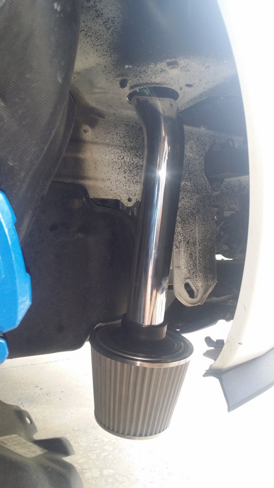
20150927_142801.jpg 20150927_142811.jpg20150927_142819.jpg 20150927_143939.jpg 


Looked like it was going to be as easy as a 90 silicon coupler and a long tube with a 45 bend. I was concerned it was folding the coupler too much reducing air flow. That was the least of my worries after I heard a CRUNCH CRACK from my MAF housing part I made.
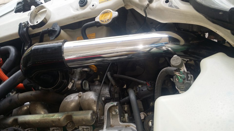
20150927_143950.jpg

Snapped right where I joined the two parts.
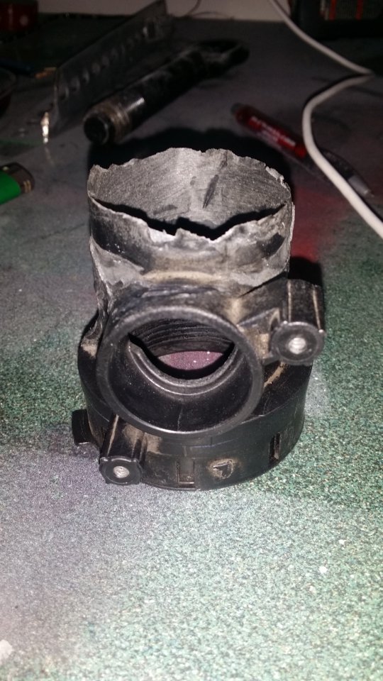
20150927_170404.jpg 20150927_170413.jpg 

Off to find a fabricator but since I'm cheap I went to exhaust repair shops first.

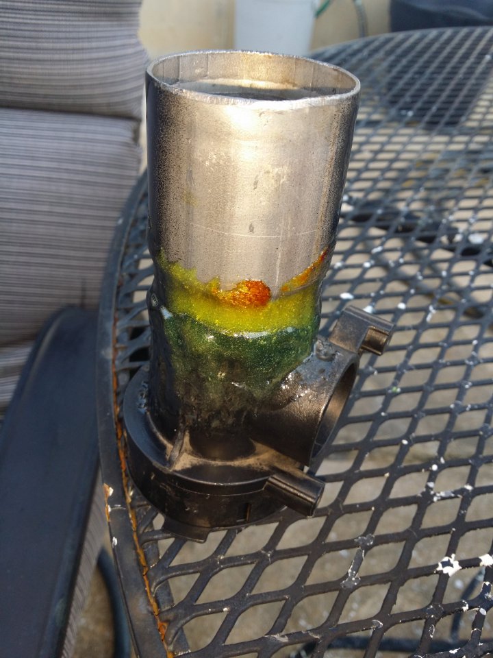
Found a exhaust tube that fit in well enough then had the guy bump out the end.
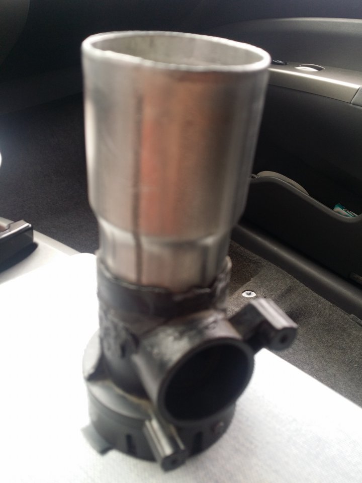
20150929_120455.jpg 


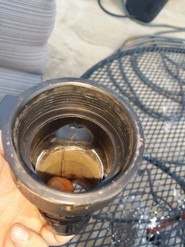
Goes down far enough it has some lip to grab.
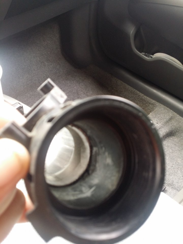
20150929_120508.jpg 20150929_120516.jpg 

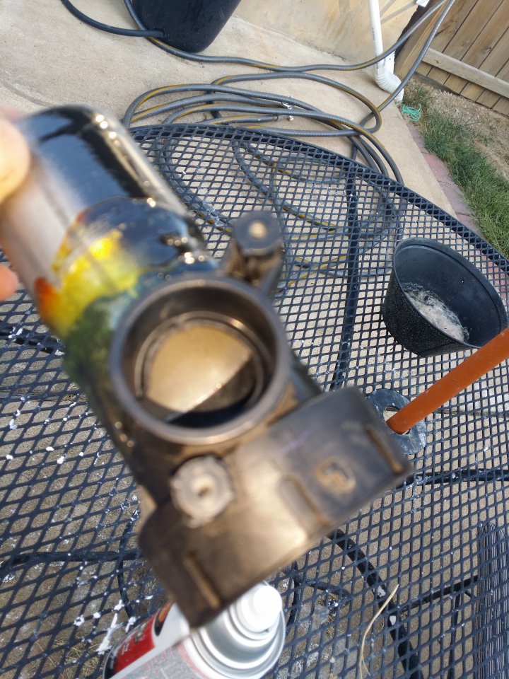
Grinded it down so I can wedge it down futher into the plastic MAF housing.
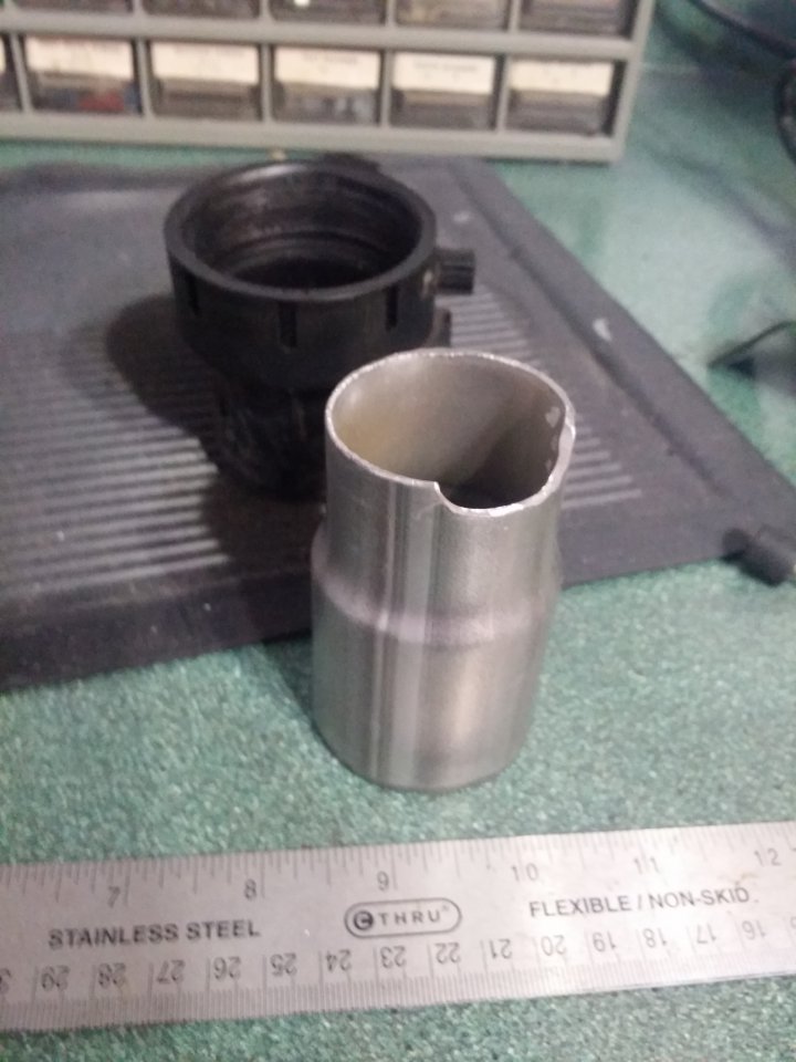
20150929_185334.jpg 

Covered in epoxy then painted to match.
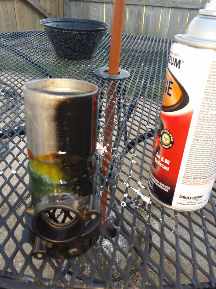
20151001_170400.jpg 20151001_170409.jpg 20151001_170418.jpg 20151001_170434.jpg


Snapchat--3729745832548025685.jpg

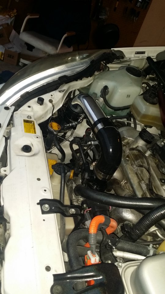
Decided to cut the whole area out to allow for more wiggle room. Wrapped the intake in duct tape then a old rubber coupler around the area I cut. Zip tied, wire and pipe taped it down, would rattle if I didn't. If you can get the intake tube in nice and neat then right on.
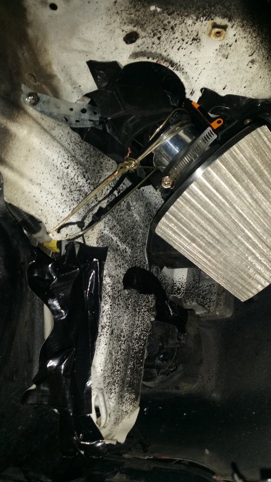
20151004_183930.jpg 

20151004_184431.jpg 

The intake tube was banging against what I guess is a metal coolant line so wrapped that area in Gorilla tape
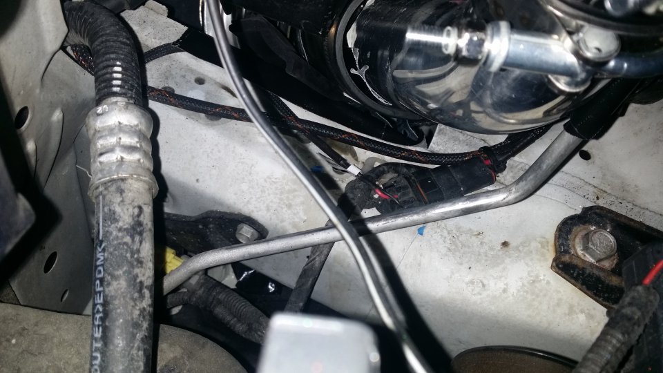
20151004_184437.jpg
Zip tied the tube to the mount for that metal tube.
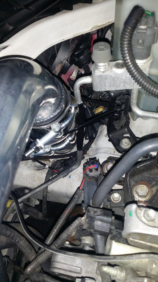
20151004_184443.jpg 


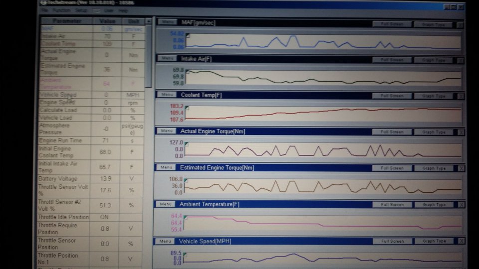
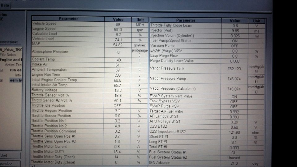
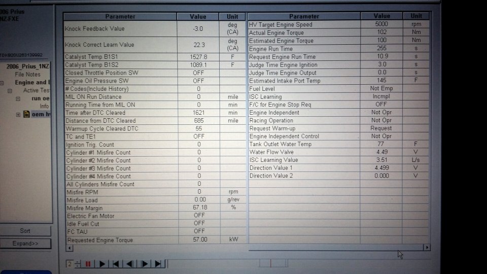
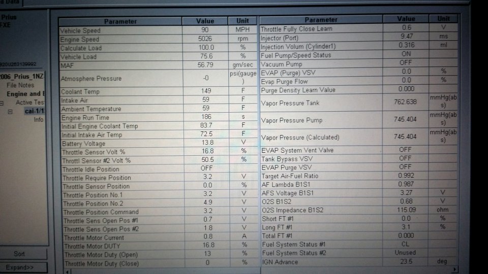
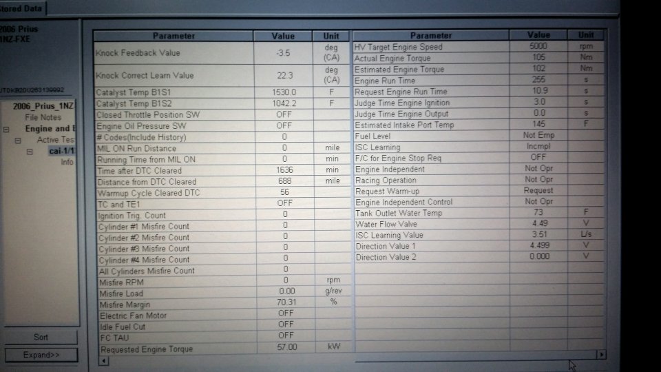
Here is some info Tech Stream gave me when I did a quick high way run with the cold air intake in. At about 90MPH there was a 5 Nm gain in torque over the stock intake so yay but sadly the over all torque decreased. Again according to TechStream so not sure how accurate it is. 
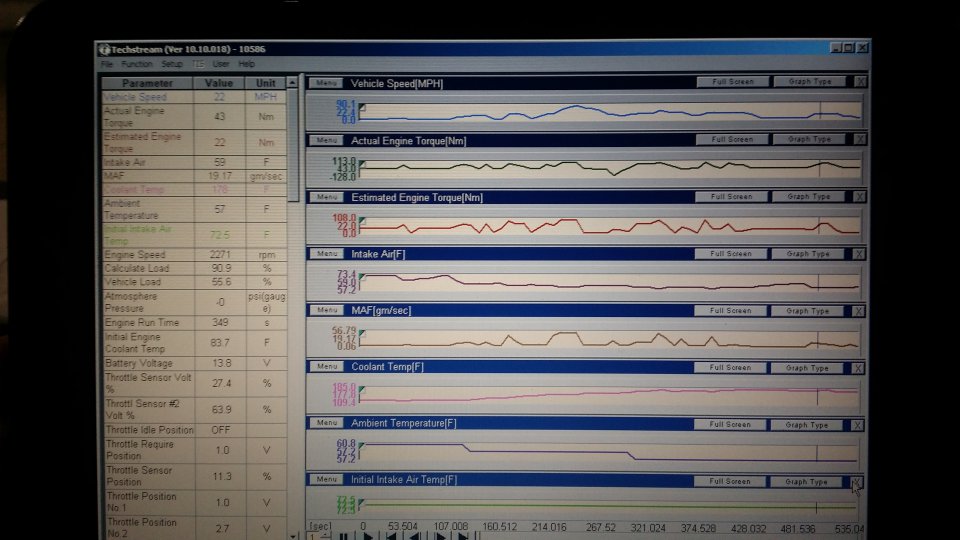
20151004_224224.jpg

Stock intake run 20151004_224459.jpg


OEM intake run
2015-10-04 22.17.55.jpg
2015-10-04 22.20.18.jpg


Cold Air Intake run 
2015-10-04 22.24.18.jpg2015-10-04 22.24.02.jpg


Wonder what Dyno results would show. We'll see if this helps at the races. More testing results will be added.
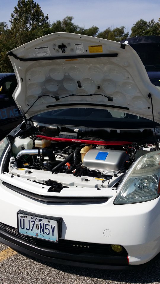


20151011_125328.jpg


Added a heat shield/splash guard. Since lowering the car I've had to mess with the wheel well cover due to rolling fenders and figure i'll add some more splash protection. Probably not needed but makes me feel better about water coming in via the wheel well, if ever.
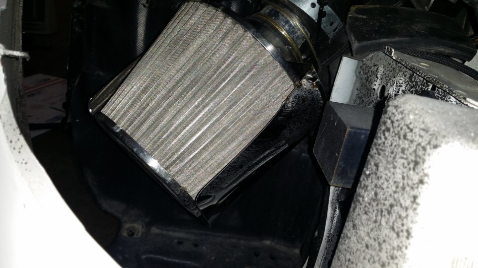
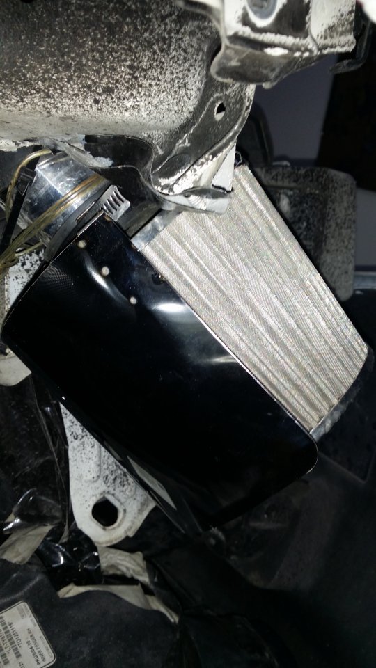
20160409_220352.jpg20160409_220313.jpg 20160409_220345.jpg

Monday, August 3, 2015

Grid Charger


GRID CHARGER


Please print out Hybrid Automotive - 2004-2009 Toyota Prius Grid Charger Installation and have it with when installing. The following is my own pictures,notes and video on my install.


I have wire for subs so ignore those. Also put dyno mat and sound deadening spray. Remove all covers in the trunk. On the driver side take out the battery holder plate. Disconnect the negative off the 12V battery so the car has no power.


20150801_193909.jpg
Remove this orange plug, it's super easy just pull up, turn notch down then whole thing comes out.

20150801_194048.jpg 

After I took the side connection cover off this is what you get. Double checked the voltage on anything you plan on touching or removing a nut off. Need to take the white plastic covers off. Check for voltage there too.

20150801_195443.jpg 

Positive on the left towards the rear bumper and ground near the front. Take off the tiny nut (think it was a 8mm) and connect the wire harness. Make sure the wires will not get pinched or in the way of anything else. Use zip ties in here too. 

20150801_200729.jpg

NEXT is connecting the fan. Reach behind and feel out the fan clip. Push down and release. Don't freak out if after you cut the fan wire and see 4 wires. Just strip them and twist the same colors together. 

20150801_202726.jpg 

Strip on the fan side too.

20150801_203512.jpg 

The bottom of the black box comes off, do not unscrew anything on it! There are two extra screws with the connectors that you will use on the bottom. Use the supplied end connections and crimp on the fan wires. This picture below shows only the fan plug connected to help give reference to the card diagram.

20150801_204413.jpg 

Zip tie the controller box best way you can. I used 4 ties.

20150802_180334.jpg

Again ignore my speaker wires and subs. Now is the test. WIth the negative still off the 12V connect the power supply to the harness then plug in power. Mine has some heat/burning smells at first but not enough to cause alarm. All fans were spinning and I got numbers on the charger so that worked!!! Was at like 211 V on the charger.

20150801_215304.jpg

Disconnect the charger then plug the negative back on the 12V. At this point I started the car to make sure it's all good which it was. Turn the car off and reconnected the charger with the harness part first. When plugging the AC power to the power supply I get a spark each time. Now the charger says about 235V.

20150801_215311.jpg 


Trunk is still apart just in case. First charge was about 15 hours long before I had to go somewhere. The battery bars on the Prius did not change. Next day I did like 8 hours. Only thing that gets hot is the charger and the controller box.20150802_180340.jpg


I always reset my trip odometer when filling up. Was at about half a tank at 37.5 MPG before it reset due to disconnecting the 12V battery. Now after about 2 days driving my MPG is 39.4. I will keep tracking and compare it to my previous MPG.

Monday, July 27, 2015

14 Impala Ghost Lights


Impala Ghost Lights 


 Remove the rubber piece in the door and remove the bolt.


Pry up the window controls and find the other bolt. There is no need to unplug the wires at this part.

Remove the little plastic cover to get to this bolt and remove.


Pull the top of the door trim up and over the lock with the windows down. Next start pulling and prying around the sides until you hear the clips.  Disconnect the door handle and the large power connector. The power connector should have a tab you pull over then wiggle the whole thing out.

Remove the top bolt from the speaker and pull upwards then out. The plug on the back is weird but will come out with a small screw driver. Roll the window back up by temporarily plugging power back in.
Both sides of this connector between the door can be pulled off. The cabin side has alot of wires in an assembly so I ran my wire under that in such a way the covers go back on as normal.

This is the inside of the door plug cover. Note my white wire coming out. There are three nipple like connectors on here. I opened it up to run the wire. To put it back you have to match up the nipples then pull until the snap in.
This is passenger side where my wire came in. There is a large squishy black piece that needs to be pulled out enough to snake the wire through. Driver side has the same thing but more electronics in the way.

Door sill needs to come up also.


Tapped directly into the footwell light and soldered. 


 Pick a good spot that the light won't be in the way or hit anything on the door.

 Here is were we drilled and mounted on the back side of the door panel.

 Connect the ran wire to the ghost light wires and solder

Found out the hard way you MUST run the wire through the black door panel cover and not the speaker hole.


Plug stuff back together.


Not bad for day time.


Do the same thing for the driver side.


 This is where we managed to get the wire to come into the cabin at.